Radar Feed Horn

2021.47.06
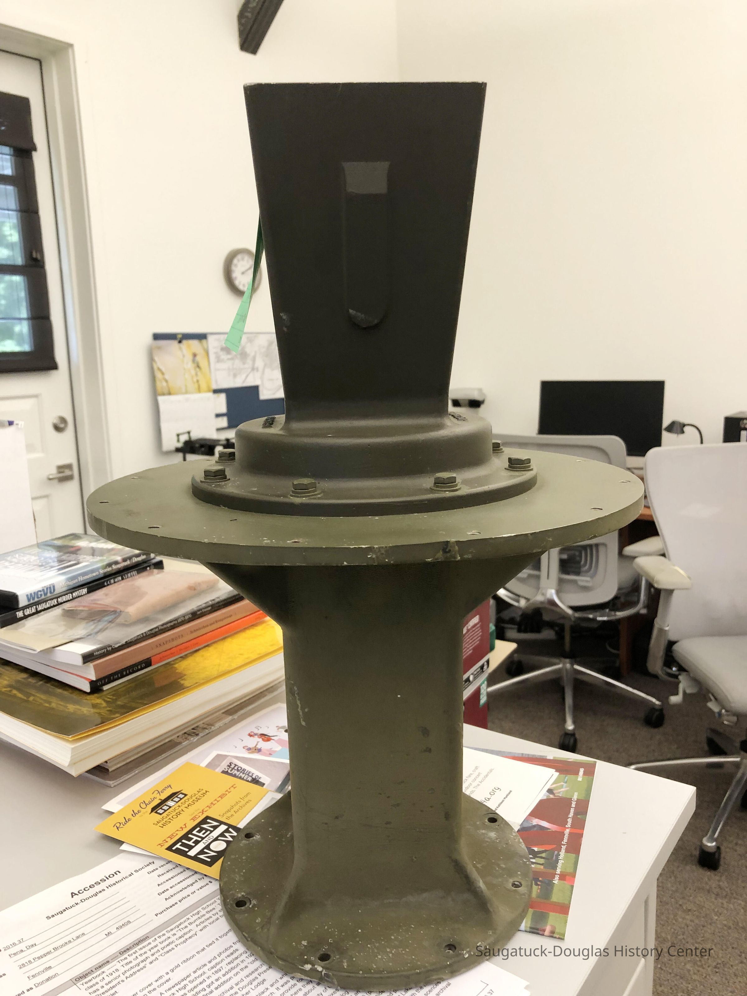
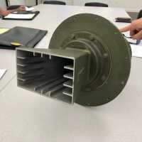
Text by Chuck Gustafson: The feed horn was mounted on the ‘nose’ of the antenna framework a little forward of where the foot of the ladder propped on the reflector presently is. The end that is up in the image faced back toward the antenna’s reflector. The other end was connected to the rectangular waveguide that traveled through a rotating joint on the antenna pedestal, then down the center of the tower and back to the transmitter and receiver in the equipment and generator building. Pulses of microwave energy from the transmitter would travel through the waveguide and exit from the end of the feed horn, spreading to the width and height of the reflector which would reflect them out away from the antenna in a beam with a carefully designed pattern spreading 1.4° wide and 30° tall with the bottom edge of the fanning beam elevated 0.5° above the lake. Any pulse encountering an aircraft would ‘echo’ back to be collected by the reflector which would concentrate and reflect the echo to the feed horn from which it would travel back down the waveguide to the receiver.
Winthers, Sally
2021.47
Peterson, Roland J. "RJ" 1926-2020
Donation
History Museum at Mt. Baldhead Park/Pump House Museum
Mount Baldhead Gap-Filler Radar Annex 1956-present
Object Label
Part 4. Feed Horn. The feed horn was mounted on the nose of the antenna framework. Pulses of energy from the radar transmitter in the building traveled up the tower, through the rotating joint on the antenna pedestal, and exited the feed horn, that spread the pulses into a wave that matched the width and height of the reflector. The reflector sent the pulses away from the antenna in a beam with a carefully designed pattern spreading 1.4° wide and 30° tall with the bottom edge of the beam elevated 0.5° above the lake. Any pulse encountering an aircraft would echo back to be collected by the reflector and sent back down to the receiver.
09/02/2021
03/31/2024


